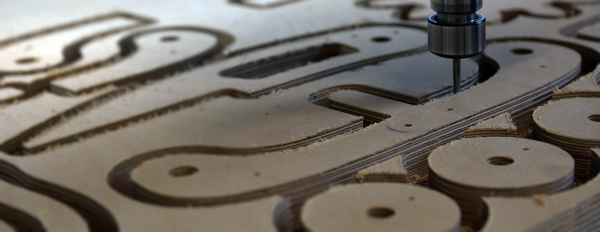
CNC technology offers complex and precise processing methods for most rigid materials. Compared to laser technology, 3-axis CNC processing makes possible both 2D cutting and the creation of more or less prominent volumes, by using the Z-axis movement of the processing tool.
Through 3-axis CNC processing, pieces can be cut on contour with a straight, inclined, or profiled edge, or pieces with linear or surface carvings in the thickness of the material, with a flat, rounded, or irregular bottom.
At Atelier 13, you can benefit from the advantages of this technology either independently, by ordering CNC cutting and/or milling services, or by ordering production and/or design services for objects whose optimal execution method is represented by CNC processing.
The use of CNC technology for material processing is applicable in various fields that require production stages. The multitude of parameters that can be controlled makes it possible to obtain pieces with complex and precise contours or volumes, from rigid materials and often with a large thickness, difficult to process by other methods
In our workshop, you can confidently rely on the advantages of laser technology when you want to cut or mill suitable materials for the purpose of obtaining: medium or large-sized pieces in exact dimensions, pieces from rigid materials with thicknesses between 1-90 mm, pieces from rigid materials that are not compatible with laser processing (for example, containing PVC) or 2.5D volumes from various materials.
The areas of applicability of CNC processing in our workshop are mainly: architecture, design, art, scenography, advertising production, presentation models, engineering, or custom furniture production.
CNC milling cutting is the mechanical cutting of the material using tools of various diameters, depending on the thickness and density of the processed material. We usually use cutting mills with thicknesses greater than or equal to 3mm, and increasing the diameters of the processing mills used brings with it an increase in the radii of the connecting contours inside, fewer passes needed to pierce the material and, implicitly, lower processing costs.
The color of the edge of the mechanically processed material with the mill is usually the same as that of the unprocessed material, and in the case of glossy materials, the edge becomes matte.
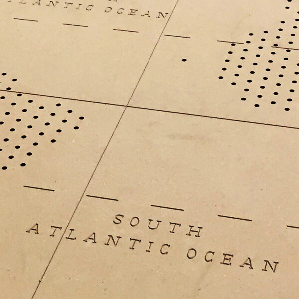
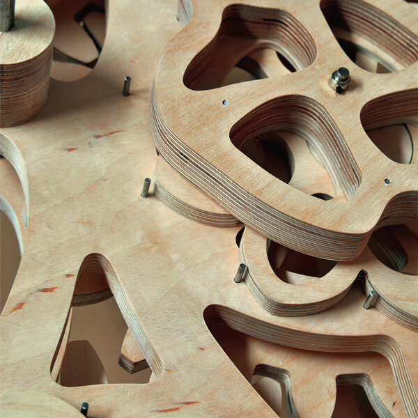
Milling channels and profiles actually refers to line engraving performed mechanically with mills of various shapes and diameters. Based on line drawings, materials can be imprinted with channels of controlled depth and width, or the edges can be processed with various profiles. The parameters that determine the appearance of milling are: the depth of processing which determines the depth of the channel, the diameter of the mill which determines its width, and the shape of the mill used which can determine the different profile of the channels – straight, V-shaped, rounded, or even with complex profiles given by mills with special shapes.
Unlike laser engraving, milling with a mill does not change the color of the material.
Surface milling or thinning/finishing is the process by which the material is thinned in the desired areas with constant depth and according to a shape dictated by the processing design.
Just like line engraving, the native color of the material will remain the same in the processed areas, and the diameters of the mills used will determine the connection radii at the inward corners of the engravings. Just like line engraving, the native color of the material will remain the same in the processed areas, and the diameters of the mills used will determine the connection radii at the inward corners of the engravings.
Projects indicating surface milling will also have indications of the depth of the processes.
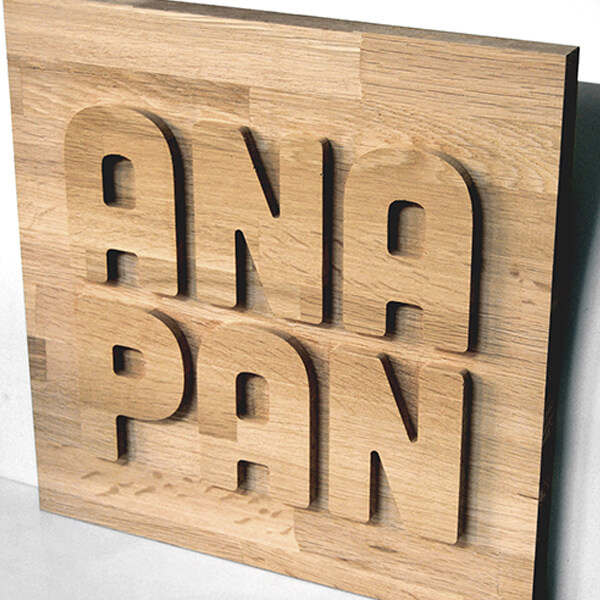
The movement modes of the processing tool in 3-axis CNC equipment allow, in addition to 2D processing, 2.5D operations that make possible volumes with straight or inclined planes at different dimensions. Essentially, we can obtain a series of 3D volumes under certain conditions, the main one being that the processing tool can sculpt into the material from above.
Such volumes involve more complex operations and can be obtained based on models designed in 3D modeling software, from materials with relatively constant density and whose milling can lead to the acquisition of smooth surfaces – polyurethane foams, solid wood, MDF, etc.
| CATEGORIES | MATERIALS | THINCKNESSES | CUTTING | MILLING |
| PLASTIC | acrylic sheets | 1.5 – 20 mm | ||
| copoliester PETG | 0.5, 1 mm | |||
| hips | 1.5, 2, 3 ** mm | |||
| CNC millable ABS * | 1,5 -1,6mm | |||
| forex | 1, 2, 3, 4, 5, 6, 8, 10 mm | |||
| polipropylene * | all thicknesses | |||
| WOODEN MATERIALS | MDF | 3, 4, 6, 8 mm | ||
| MDF > 10 mm ** | 10, 12, 18, 22, 24, 40 mm | |||
| poplar plywood | 4, 6, 8 mm | |||
| Different essences – plywood ** | toate grosimile | |||
| Solid wood * | All thicknesses < 7 cm | |||
| balsa | all thicknesses | |||
| cork | 1, 2, 3 mm | |||
| cork | 5mm, >5 mm ** | |||
| CELLULOSIC MATERIALS | paper | all thicknesses | ||
| duplex | all thicknesses | |||
| cardboard for bookbinding | all thicknesses | |||
| passepartout | all thicknesses | |||
| corrugated board | all thicknesses | |||
| kapa line, foam x | all thicknesses | |||
| METALS | Stainless steel | all thicknesses | ||
| aluminium | all thicknesses | |||
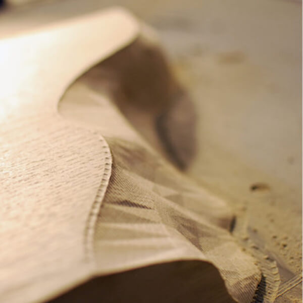
| OTHER MATERIALS | textiles | all thicknesses | ||
| felt | all thicknesses | |||
| natural leather | all thicknesses | |||
| sponge | all thicknesses | |||
| polyurethane foam | 0-8 cm *** | |||
| polystiyene * | 0-8 cm |
* materials that we don’t keep in stock
** materials that we bring with special order
*** we keep in stok only for some thicknesses
To place a CNC processing order, you need to send us a 2D vectorial design of the desired parts, made from closed polylines, to a 1:1 scale in mm. In this design, mark with different colors the types of processing used – cutting, linear milling, or surface milling. Additionally, you need to specify the milling depths for any millings and any other additional information that is important for obtaining the desired result.
IFor 2.5D volumes, you need to send us the three-dimensional file of the parts at a 1:1 scale.
It’s good to know that mechanical processing will always determine rounded connections at inner angles, only allowing sharp angles in the case of protruding corners. The thicker the material, the larger the diameter of the used milling bit, and consequently the rounding radius at the inner angles.
For 2D cutting and linear milling operations, for ease of communication of the desired result and to avoid interpretation problems, we recommend using the template below, which can be imported to scale in any vectorial drawing software.
We recommend considering the following mentions regarding file preparation:
Following the analysis of the files and the requirements of the project, you will receive our offer based on material consumption and the estimated quantity or processing time.

